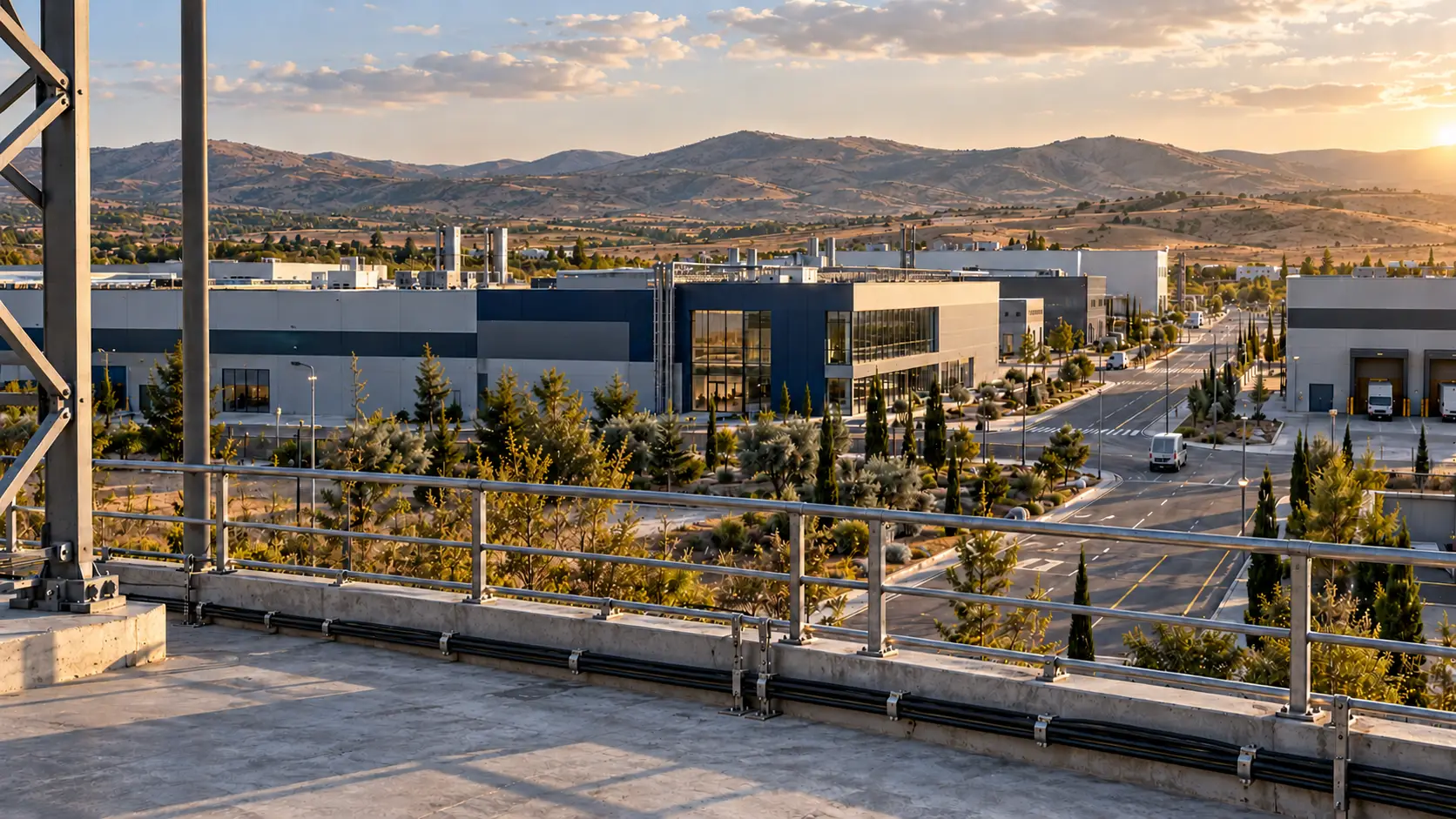
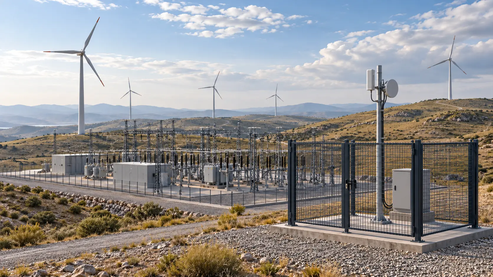
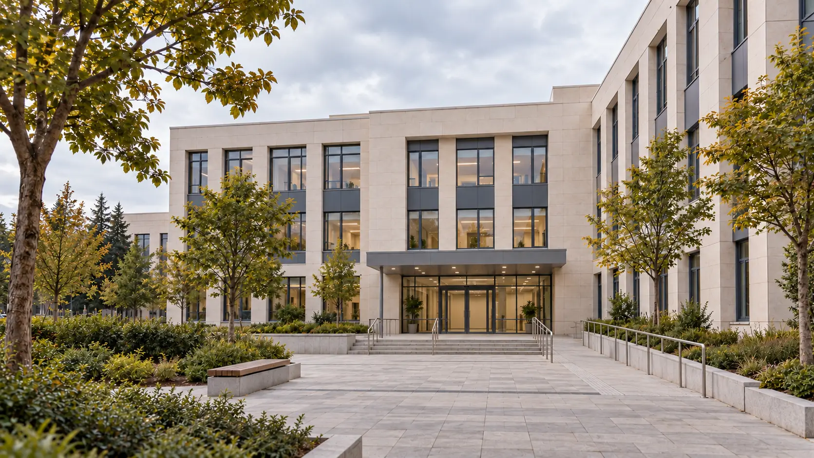
Survey and route analysis
Site survey, inventory of existing ducts and infrastructure, and technical and cost comparison of route options.

We deliver backbone, metro, campus and in-building fibre infrastructure end to end: survey, design, field deployment, testing and documentation from a single team.
The quality of a fibre route is decided long before the cable goes in. If the route, cable type, splice points and optical power budget are not planned correctly, even the best active equipment cannot deliver the expected performance.
Mixnet’s engineering team starts every project with a site survey, carries out the deployment with its own crews, verifies every route with measurements and tests, and documents it as built.
Site survey, inventory of existing ducts and infrastructure, and technical and cost comparison of route options.
Construction drawings covering cable, splice point, ODF and cabinet placement; optical power budget and capacity planning.
Coordinating right-of-way, excavation and infrastructure permits with the relevant authorities and operators.
Underground duct and micro-trenching, aerial routes (ADSS) and vertical/horizontal in-building fibre cabling.
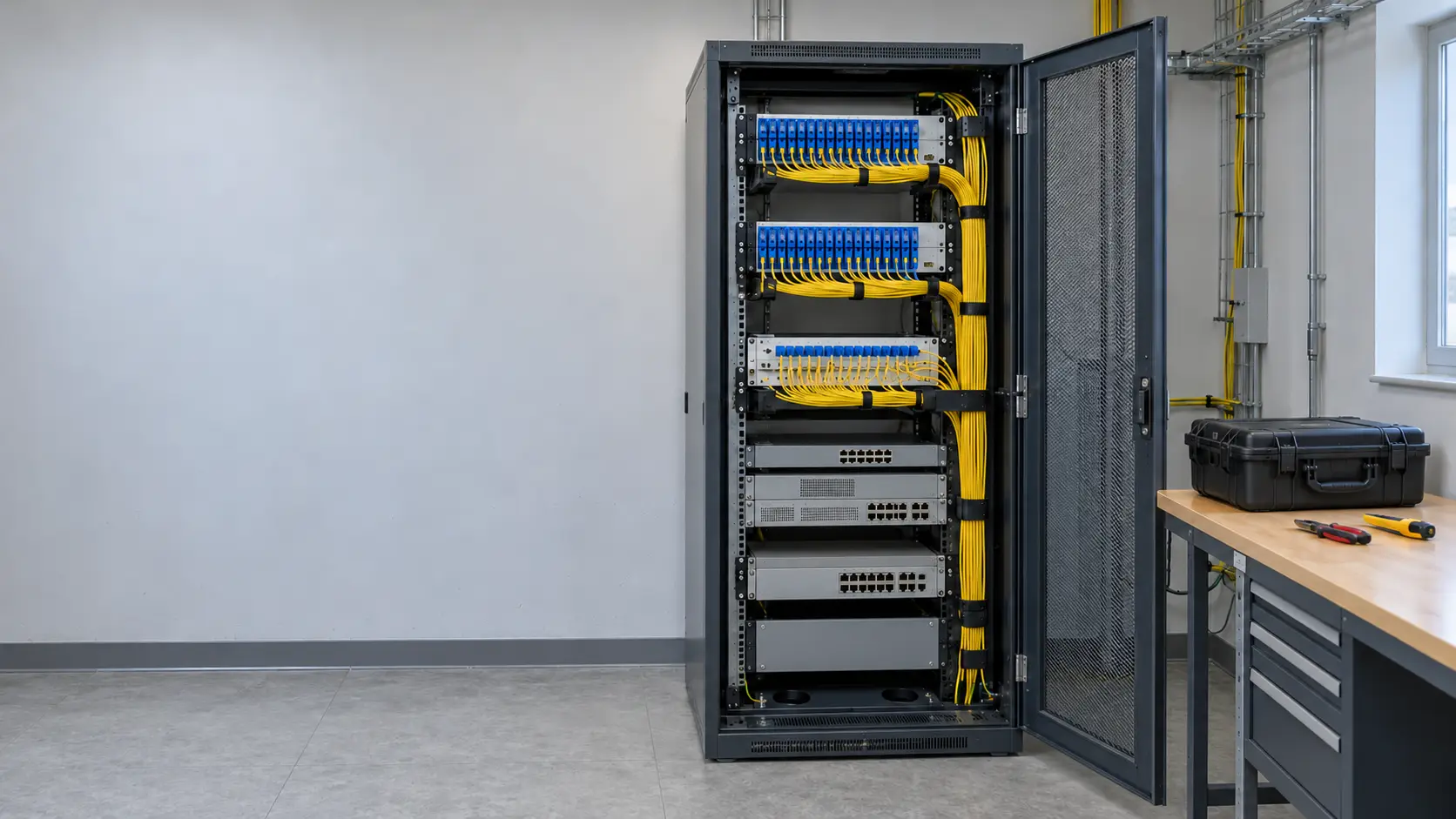
Splice closure, ODF and patch panel terminations; low-loss fusion splicing.
Bidirectional OTDR measurements, optical power and insertion loss tests; reporting for every fibre.
As-built drawings of the deployed route and documentation recorded in a geographic information system.
Planned maintenance, OTDR fault location and rapid repair.
An OTDR trace shows the loss at every connector, splice and splitter along the route, together with its distance. These traces are kept as the reference record of each route and used for comparison when a fault occurs.
| Cable types | Single-mode G.652.D and bend-insensitive G.657, micro cable, aerial (ADSS) |
|---|---|
| Termination | Fusion splicing, ODF and patch panel; SC/APC, LC/UPC connectors |
| Measurement | OTDR (1310 / 1550 nm), optical power meter, visual fault locator |
| Applications | Backbone and metro routes, organised industrial zones (OSB), campus, in-building, FTTx |
| Documentation | Test reports, as-built drawings, GIS layers |
Let’s assess your needs and your site together, and work out the right architecture and project plan for you.